Peripherals#
%connect serial:///dev/ttyAMA1
Connected to robot-stm32 @ serial:///dev/ttyAMA1
Configuration#
/boot/config.txt: add
[pi4]
dtoverlay=uart3
dtoverlay=uart4
enable_uart=0
Balena: configure dtoverlay from the dashboard.
Overlay enable_uart=0 disables the console UART on pins 8, 10. No need to disable if pins are not connected (but then there is no way this can work with a Pi 3, probably ok).
UART Assignments (Pi 4):
Pi 4                      STM32
/dev/ttyAMA1   uart3      uart6 (REPL)
/dev/ttyAMA2   uart4      uart3 (dfu, robot comm)
GPIO Pins:
BOOT0   = 13 (GPIO27)
SHUT_DN = 33 (GPIO13)     shutdown button input (active low)
nRST    = 40 (GPIO21)
AUX     = 36 (GPIO16)     stm32: AUX
                          stm32: PWR_EN: pull low to cut main (5V) power supply
                          stm32: V12_DIV: 12V input / 7.8
GPIO#
List of available GPIOs and their capabilities:
# pin alternate functions

from pyb import Pin

print("{:15} {:4} {}".format('board name', 'name', 'alternate functions'))
for p in sorted(dir(Pin.board)):
    if '__' in p: continue
    pin = Pin(p)
    names = pin.names()
    print("{:15} {:4} {}".format(names[1], names[0], pin.af_list()))
Show code cell output
board name      name alternate functions
AIN1            C5   []
AIN2            C1   []
AUX             B13  [Pin.AF1_TIM1, Pin.AF5_SPI2, Pin.AF7_USART3]
BATTERY_MONITOR A3   [Pin.AF1_TIM2, Pin.AF2_TIM5, Pin.AF3_TIM9, Pin.AF7_USART2]
BIN1            C3   [Pin.AF5_SPI2]
BIN2            A4   [Pin.AF5_SPI1, Pin.AF7_USART2]
BOOT1           B2   []
D8              C0   []
ENC_A1          A6   [Pin.AF1_TIM1, Pin.AF2_TIM3, Pin.AF3_TIM8, Pin.AF5_SPI1, Pin.AF9_TIM13]
ENC_A2          A7   [Pin.AF1_TIM1, Pin.AF2_TIM3, Pin.AF3_TIM8, Pin.AF5_SPI1, Pin.AF9_TIM14]
ENC_B1          B6   [Pin.AF2_TIM4, Pin.AF4_I2C1]
ENC_B2          B7   [Pin.AF2_TIM4, Pin.AF4_I2C1]
FLASH_CS        A15  [Pin.AF1_TIM2, Pin.AF1_TIM2, Pin.AF5_SPI1]
FLASH_MISO      B4   [Pin.AF2_TIM3, Pin.AF5_SPI1]
FLASH_MOSI      B5   [Pin.AF2_TIM3, Pin.AF5_SPI1]
FLASH_SCK       B3   [Pin.AF1_TIM2, Pin.AF5_SPI1]
NC_A0           A0   [Pin.AF1_TIM2, Pin.AF1_TIM2, Pin.AF2_TIM5, Pin.AF3_TIM8, Pin.AF7_USART2]
NC_A1           A1   [Pin.AF1_TIM2, Pin.AF2_TIM5, Pin.AF7_USART2]
NC_A2           A2   [Pin.AF1_TIM2, Pin.AF2_TIM5, Pin.AF3_TIM9, Pin.AF7_USART2]
D8              C0   []
NSTBY           C2   [Pin.AF5_SPI2]
PWM_A           B15  [Pin.AF1_TIM1, Pin.AF3_TIM8, Pin.AF5_SPI2, Pin.AF9_TIM12]
PWM_B           A5   [Pin.AF1_TIM2, Pin.AF1_TIM2, Pin.AF3_TIM8, Pin.AF5_SPI1]
PWR_EN          B14  [Pin.AF1_TIM1, Pin.AF3_TIM8, Pin.AF5_SPI2, Pin.AF7_USART3, Pin.AF9_TIM12]
RX              B11  [Pin.AF1_TIM2, Pin.AF4_I2C2, Pin.AF7_USART3]
RX_AUX          C7   [Pin.AF2_TIM3, Pin.AF3_TIM8, Pin.AF8_USART6]
SCL             B8   [Pin.AF2_TIM4, Pin.AF3_TIM10, Pin.AF4_I2C1, Pin.AF9_CAN1]
SDA             B9   [Pin.AF2_TIM4, Pin.AF3_TIM11, Pin.AF4_I2C1, Pin.AF5_SPI2, Pin.AF9_CAN1]
SD_CK           C12  [Pin.AF7_USART3]
SD_CMD          D2   [Pin.AF2_TIM3]
SD_D0           C8   [Pin.AF2_TIM3, Pin.AF3_TIM8, Pin.AF8_USART6]
SD_D1           C9   [Pin.AF2_TIM3, Pin.AF3_TIM8]
SD_D2           C10  [Pin.AF7_USART3]
SD_D3           C11  [Pin.AF7_USART3]
SD_DETECT       B12  [Pin.AF1_TIM1, Pin.AF5_SPI2, Pin.AF7_USART3]
SWCLK           A14  []
SWDIO           A13  []
TX              B10  [Pin.AF1_TIM2, Pin.AF4_I2C2, Pin.AF5_SPI2, Pin.AF7_USART3]
TX_AUX          C6   [Pin.AF2_TIM3, Pin.AF3_TIM8, Pin.AF8_USART6]
USB_DM          A11  [Pin.AF1_TIM1, Pin.AF9_CAN1]
USB_DP          A12  [Pin.AF1_TIM1, Pin.AF9_CAN1]
USB_ID          A10  [Pin.AF1_TIM1]
USB_VBUS        A9   [Pin.AF1_TIM1]
V12_DIV         C4   []
Motor Controller#
I use HPCB micro gear motors with extended shaft (to mount the encoder magnet) and 210:1 gear ratio.
The motor controller comprises two H-bridges to control the speed and direction of the motors and magnetic encoders to capture the rotational speed.
H-bridges#
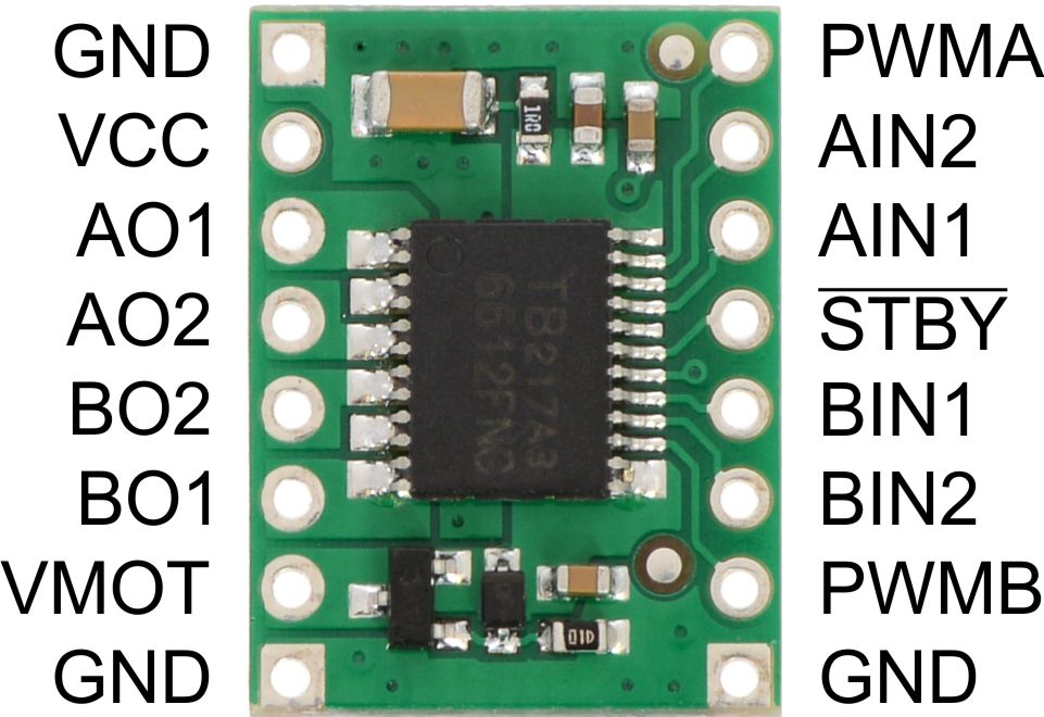
The figure below shows the TB6612 motor controller. It is wired to the STM32 as follows:
Channel A control: PWMA, AIN1, AIN2
Channel B control: PWMB, BIN1, BIN2
The xIN1 and xIN2 determine its state as follows:
Function |
IN1 |
IN2 |
Notes |
|---|---|---|---|
Forward |
L |
H |
|
Reverse |
H |
L |
|
Brake |
H |
H |
speed=0 has same effect |
Coast (Z) |
L |
L |
The TB6612 class maps the desired speed input to the appropriate control signals:
%cat /flash/lib/tb6612.py
Show code cell output
"""
TB6612 motor driver.

Example:

from pyb import Pin, Timer
from tb6612 import TB6612
import time

freq = 10_000
tim = Timer(8, freq=freq)

motor1 = TB6612(
    tim.channel(3, Timer.PWM_INVERTED, pin=Pin('PWM_A')),
    Pin('AIN1', mode=Pin.OUT_PP),
    Pin('AIN2', mode=Pin.OUT_PP)
)

motor2 = TB6612(
    tim.channel(1, Timer.PWM_INVERTED, pin=Pin('PWM_B')),
    Pin('BIN1', mode=Pin.OUT_PP),
    Pin('BIN2', mode=Pin.OUT_PP)
)

nstby = Pin('NSTBY', mode=Pin.OUT_PP)
nstby.value(1)

motor1.speed(30)
motor2.speed(-83)

time.sleep(5)
nstby.value(0)
"""

class TB6612:

    def __init__(self, pwm, scale, in1, in2):
        self.pwm = pwm
        self.scale = scale
        self.in1 = in1
        self.in2 = in2

    def speed(self, speed:float):
        """Set motor speed (duty cycle), range +/- 100."""
        if speed < 0:
            self.in1.value(0)
            self.in2.value(1)
        else:
            self.in1.value(1)
            self.in2.value(0)
        speed *= self.scale
        self.pwm.pulse_width(int(abs(speed)))
Example:
from tb6612 import TB6612
from pyb import Pin, Timer

# motor power control
nstby = Pin('NSTBY', mode=Pin.OUT_PP)
nstby.value(0)

# motors
pwm_timer = Timer(8, freq=10_000)
scale = (pwm_timer.period()+1)/100

motor1 = TB6612(
    pwm_timer.channel(3, Timer.PWM_INVERTED, pin=Pin('PWM_A')),
    scale,
    Pin('AIN1', mode=Pin.OUT_PP),
    Pin('AIN2', mode=Pin.OUT_PP)
)

motor2 = TB6612(
    pwm_timer.channel(1, Timer.PWM_INVERTED, pin=Pin('PWM_B')),
    scale,
    Pin('BIN1', mode=Pin.OUT_PP),
    Pin('BIN2', mode=Pin.OUT_PP)
)
Connected to robot-stm32 @ serial:///dev/ttyAMA1
Start motors: if everything is wired correctly, the motors will spin when running the code in next cell.
from time import sleep

# enable TB6612
nstby.value(1)

for speed in range(0, 101, 20):
    # set desired speed (PWM duty cycle)
    motor1.speed(speed)
    motor2.speed(speed)
    sleep(1)

motor1.speed(0)
motor2.speed(0)
nstby.value(0)
Encoder#
Just like a car, motor speed depends on load. Encoders can be used to measure the position (and, by taking the derivative, speed).
I’ve chosen magnetic encoders:
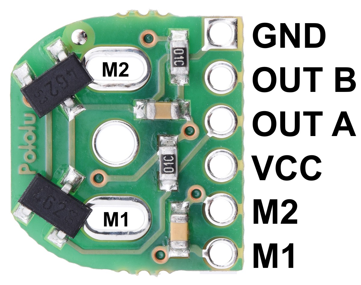
Fig. 26 Magnetic Encoder breakout boards.#
A wheel with several magnetic zones with with alternating magnetization mounted to the shaft to the motor passes two magnetic sensors (the black components on the board) to produce electrical pulses. The STM32 has built-in counters to tally up these pulses.
!cat code/stm32/lib/encoder16.py
Show code cell output
from pyb import Pin, Timer

"""
Encoder readout for STM32 16-bit timers. Corrects for counter over/under-flow.
"""

class Encoder16:

    def __init__(self, timer_no, ch1_pin, ch2_pin, af):
        pin_a = Pin(ch1_pin, Pin.AF_PP, pull=Pin.PULL_NONE, af=af)
        pin_b = Pin(ch2_pin, Pin.AF_PP, pull=Pin.PULL_NONE, af=af)
        timer = Timer(timer_no, prescaler=0, period=0xffff)
        channel = timer.channel(1, Timer.ENC_AB)
        self._timer = timer
        self._sum = 0
        self._cnt = timer.counter()

    def count(self):
        c = self._timer.counter()
        if c-self._cnt > 0x8fff:
            print("under")
            self._sum -= 0x10000
        if self._cnt-c > 0x8fff:
            print("over")
            self._sum += 0x10000
        self._cnt = c
        return self._sum + c


"""
Example:

enc = Encoder16(3, 'ENC_B1', 'ENC_B2', Pin.AF2_TIM3)

last = enc.count()
while True:
    c = enc.count()
    if abs(last-c) > 5:
        last = c
        print(f"{c:6d}")
"""
from encoder16 import Encoder16
from pyb import Pin

enc1 = Encoder16(4, 'ENC_A1', 'ENC_A2', Pin.AF2_TIM4)
enc2 = Encoder16(3, 'ENC_B1', 'ENC_B2', Pin.AF2_TIM3)
A complete example:
import time

# enable TB6612
nstby.value(1)

last1 = enc1.count()
last2 = enc2.count()

for duty in range(0, 101, 20):
    motor1.speed(duty)
    motor2.speed(duty)
    time.sleep(0.5)
    cnt1 = enc1.count()
    cnt2 = enc2.count()
    print(f"{duty:3d}  cnt1={cnt1:6d}  cnt2={cnt2:6d}  speed1={cnt1-last1:6d}  speed2={cnt2-last2:6d}")
    last1 = cnt1
    last2 = cnt2

nstby.value(0)
  0  cnt1=     0  cnt2=     0  speed1=     0  speed2=     0
 20  cnt1=   846  cnt2=   912  speed1=   846  speed2=   912
 40  cnt1=  2959  cnt2=  3081  speed1=  2113  speed2=  2169
 60  cnt1=  6282  cnt2=  6500  speed1=  3323  speed2=  3419
 80  cnt1= 10688  cnt2= 11071  speed1=  4406  speed2=  4571
100  cnt1= 15835  cnt2= 16711  speed1=  5147  speed2=  5640
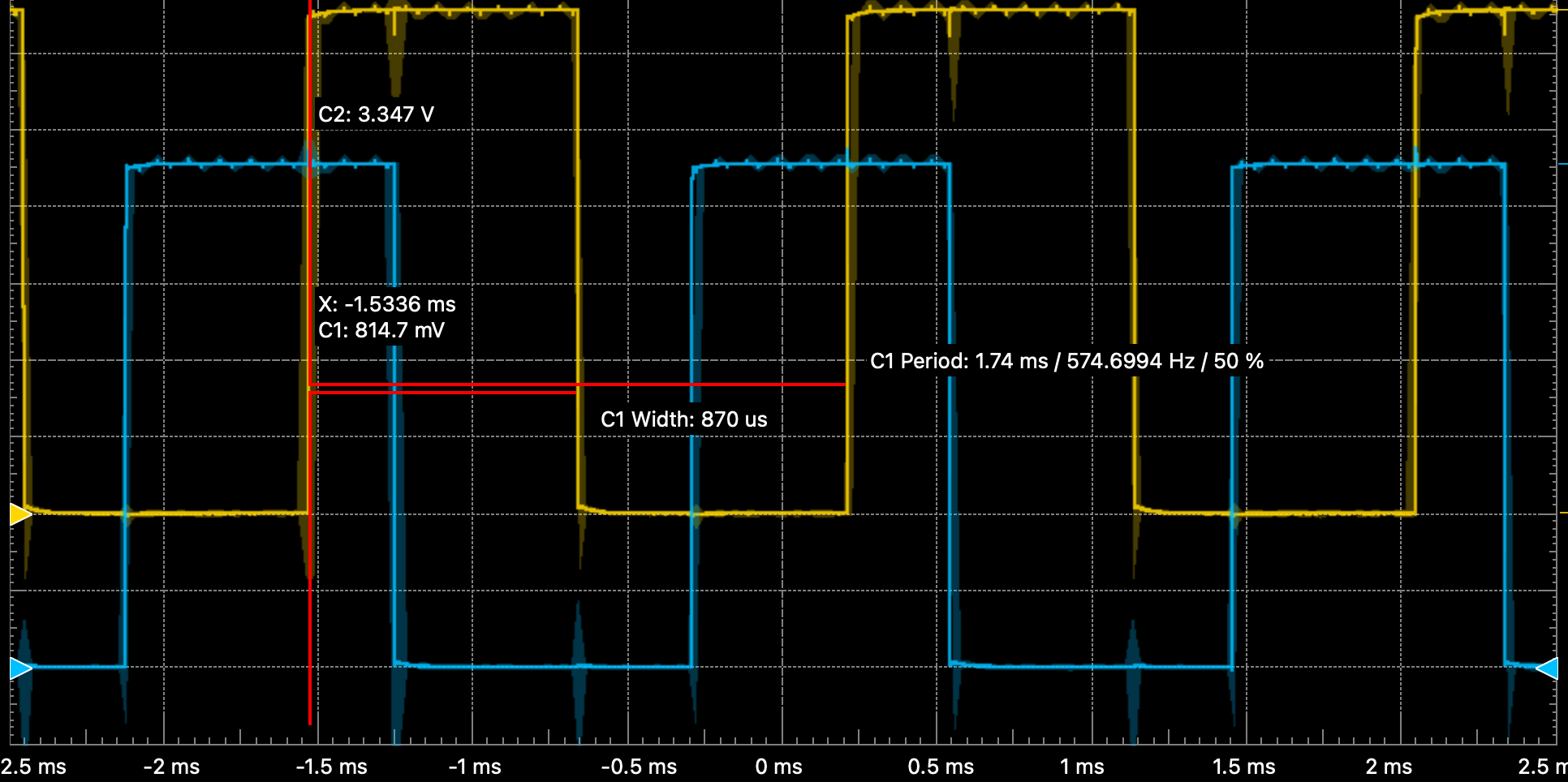
Fig. 27 Quadrature encoder signals for motor duty = 40%.#
The the output period as a function of duty cycles is
Duty [%] |
Period [ms] |
|---|---|
10 |
14.4 |
40 |
1.74 |
100 |
0.68 |
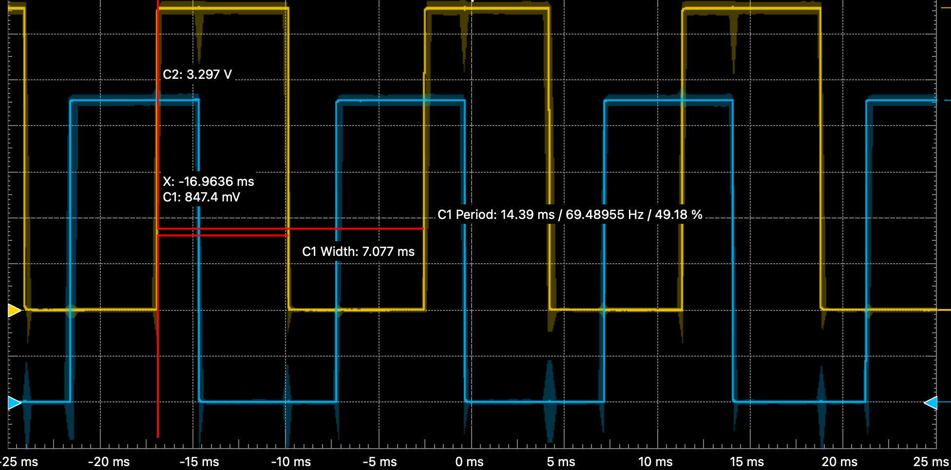
Fig. 28 Encoder output for duty = 10%.#
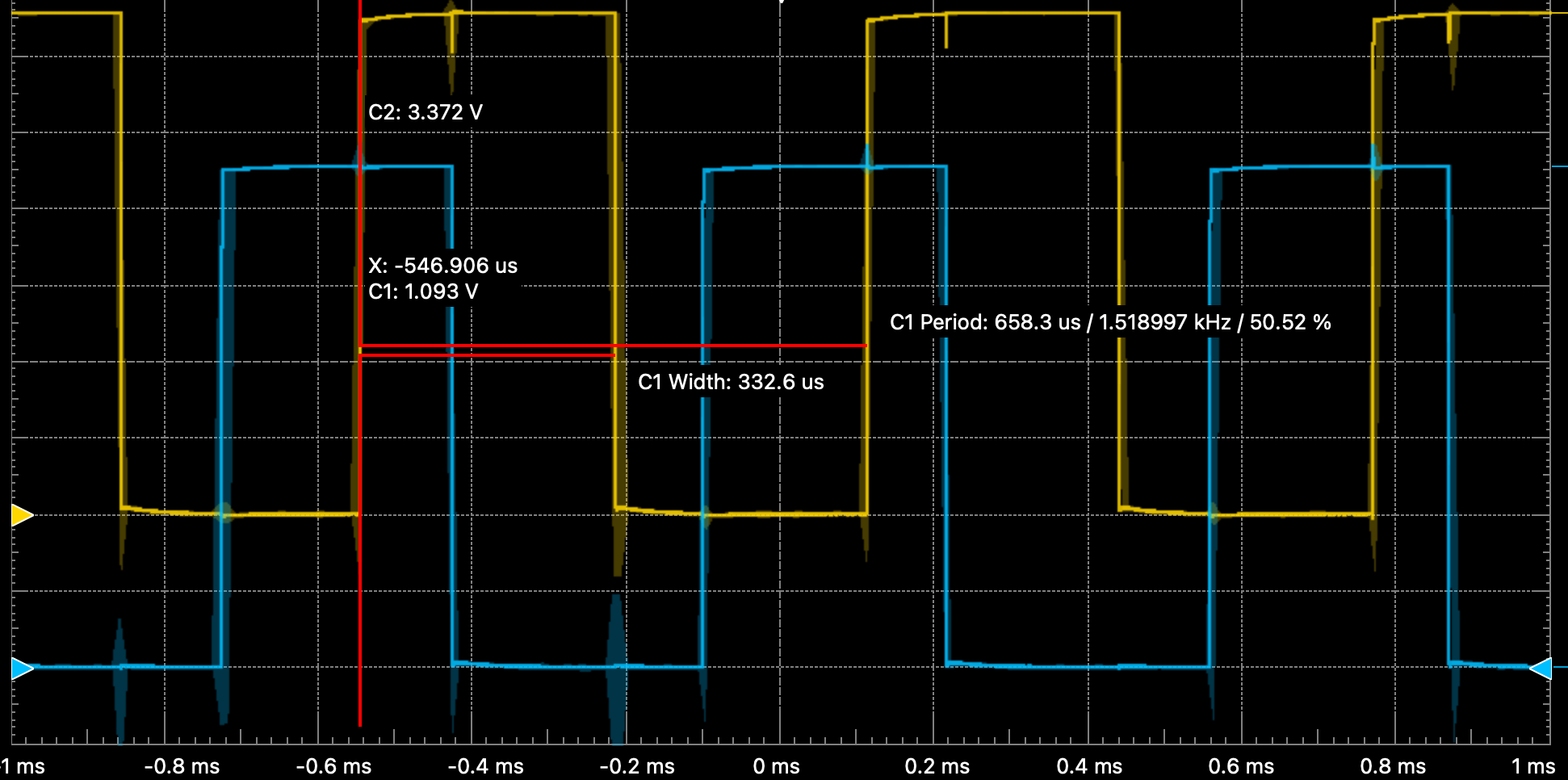
Fig. 29 Encoder output for duty = 100%.#
At low rotation speeds, the resolution of quadrature encoders is poor. It can possible be improved by measuring the pulse width or period.
Use the code below to estimate the number of counts for a full turn of the wheel. Start the measurement, then carefully turn the wheel by hand. The value depends on the encoder and motor gear ratio. For my motors it is about 1800 counts per revolution. With the 8cm wheel diameter, this amounts to 25cm displacement or 0.14mm/count.
IMU#
To balance on two wheels, the robot needs to know about the direction of gravity. Specifically, we want to know the pitch angle in the figure below.
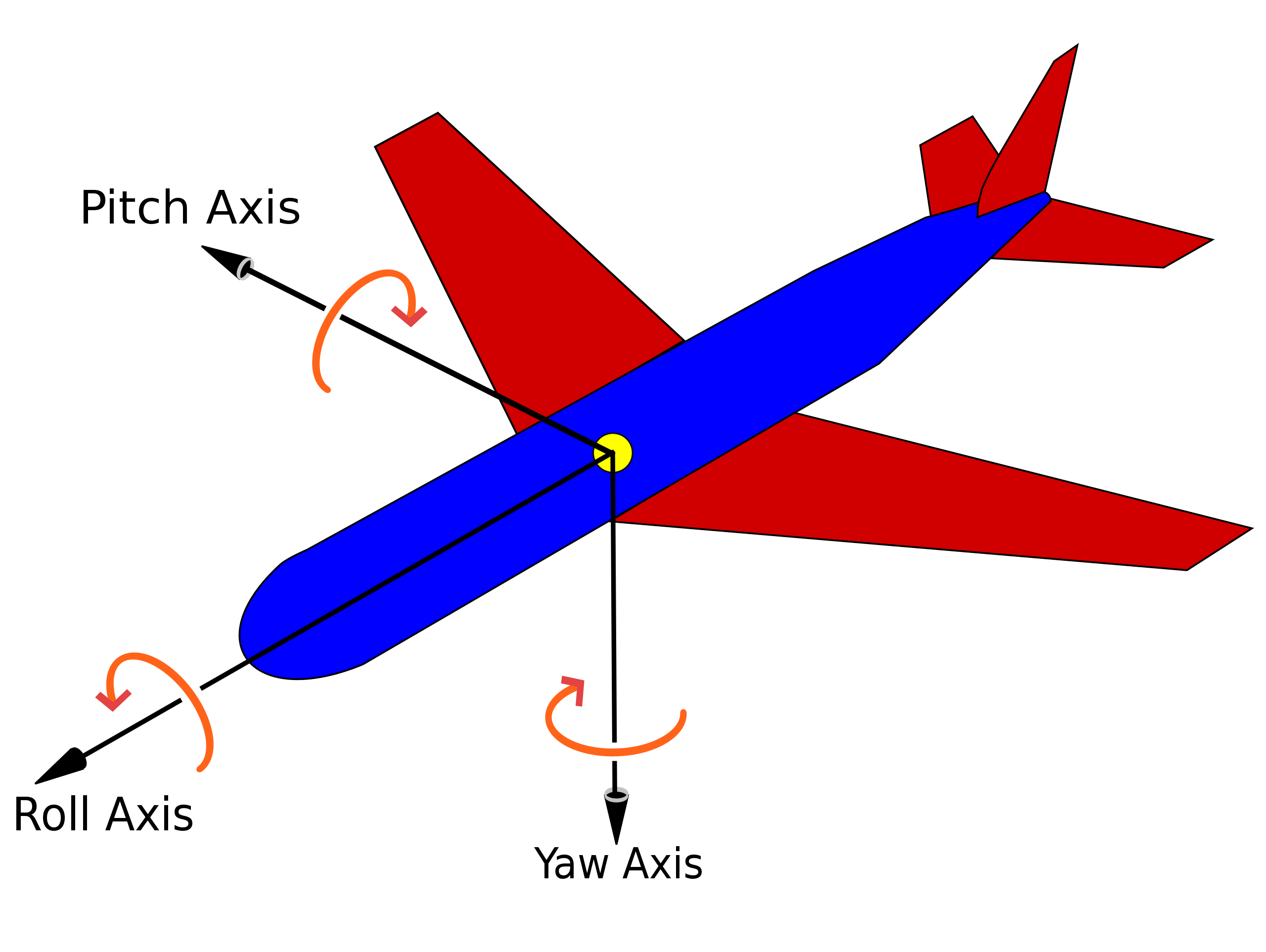
Fig. 30 Pitch, roll, and heading.#
Accelerometers and gyroscopes are perfect for this task. We will look at two solutions - one using a BNO055 IMU with on-board motion processor that directly outputs quaternions from which gravity can be calculated.
The other option uses a complementary filter to extract gravity from raw accelerometer and gyroscope output.
Below is the code using quaternions and the output from flipping the robot over.
from bno055 import BNO055, NDOF_FMC_OFF_MODE, QUAT_DATA
from machine import I2C
from time import sleep_ms
import math

RAD2DEG = 180/math.pi

# init
i2c = I2C(1, freq=400_000)
imu = BNO055(i2c, crystal=True, transpose=(2, 0, 1), sign=(0, 0, 1))
imu.mode(NDOF_FMC_OFF_MODE)
sleep_ms(800)

# read sensor and compute pitch angle
for i in range(10):
    imu.iget(QUAT_DATA)
    w = imu.w/(1<<14)
    x = imu.x/(1<<14)
    y = imu.y/(1<<14)
    z = imu.z/(1<<14)
    sinp = 2 * (w * y - z * x)
    if abs(sinp) >= 1:
        # use 90 degrees if out of range
        pitch = math.copysign(math.pi / 2, sinp)
    else:
        pitch = math.asin(sinp)
    pitch *= RAD2DEG
    print(f"{pitch:8.2f}")
    sleep_ms(500)
  -88.01
  -88.01
  -87.82
  -54.62
  -46.12
  -29.56
    3.47
   42.27
   61.86
   83.53
A little bit optimized:
from bno055 import BNO055, NDOF_FMC_OFF_MODE, QUAT_DATA
from machine import I2C
from time import sleep_ms
import math

_RAD2DEG = 180/math.pi
_90DEG = 0.5 * math.pi
_QUAT_SCALE = 1/(2<<26)

# init
i2c = I2C(1, freq=400_000)
imu = BNO055(i2c, crystal=True, transpose=(2, 0, 1), sign=(0, 0, 1))
imu.mode(NDOF_FMC_OFF_MODE)
sleep_ms(800)

# read sensor and compute pitch angle
for i in range(10):
    imu.iget(QUAT_DATA)
    sinp = _QUAT_SCALE * (imu.w * imu.y - imu.z * imu.x)
    if abs(sinp) >= 1:
        # use 90 degrees if out of range
        pitch = math.copysign(_90DEG, sinp)
    else:
        pitch = math.asin(sinp)
    pitch *= _RAD2DEG

    print(f"{pitch:8.2f}")
    sleep_ms(500)
  -88.19
  -88.15
  -42.03
    5.38
   52.51
   75.75
   42.02
   23.82
   46.48
   76.74
Complementary Filter#
The code below reports the computation time (including reading the sensor) and orientation from:
accelerometers only
gyroscope only
complementary filter combining accelerometer and gyroscope data
Euler angle computed by BNO055
The third option is robust and ideal for low-cost inertial sensors without on-board processing.
# rotate about short side of chip

import time, math, gc
from machine import I2C as I2C
from pyb import Pin
from bno055 import BNO055

tau = 0.2
Ts = 0.02
ALPHA = tau / (tau+Ts)
RAD_TO_DEG = 180/math.pi

i2c = I2C(1, freq=400_000)

imu = BNO055(i2c)
time.sleep(1)

a_off = 0
g_phi = -90
c_phi = 0

t_last = time.ticks_us()

dt = 0

print("{:>8s} {:>6s} {:>6} {:>6} {:>6}".format("dt [us]", "xcell", "gyro", "comp", "bno055"))
for i in range(1000):
    # xcell
    ax, ay, az = imu.accel()
    a_phi = math.atan2(ay, az)*RAD_TO_DEG - a_off
    if i == 0: a_off = a_phi+90

    # gyro
    rx, ry, rz = imu.gyro()
    g_phi += rx * Ts * 0.5  # why 0.5?

    # complementary
    c_phi = ALPHA * (c_phi + rx * Ts) + (1-ALPHA) * a_phi

    # euler
    _, _, e_phi = imu.euler()

    if i % 50 == 0:
        print("{:8d} {:6.0f} {:6.0f} {:6.0f} {:6.0f}".format(int(dt), a_phi, g_phi, c_phi, -e_phi-90))

    # clean slate
    gc.collect()

    # sleep off extra time
    t_new = time.ticks_us()
    dt = time.ticks_diff(t_new, t_last)
    t_last = t_new
    time.sleep(Ts-dt*1e-6)
 dt [us]  xcell   gyro   comp bno055
       0     -0    -90     -0    -91
   17999    -90    -90    -89    -91
   10447    -90    -90    -90    -91
    5354   -113   -111   -117   -114
    7995   -132   -131   -137   -134
    5399   -157   -153   -161   -158
    2593   -173   -168   -177   -176
   11001   -197   -187   -199   -196
    9994   -217   -206   -220   -216
   10603   -234   -221   -236   -233
   15108   -243   -231   -245   -244
   11001   -256   -242   -258   -256
    8185     84   -256   -123     88
    3003     90   -256     84     88
    8608     90   -256     90     88
    7747     90   -256     90     88
    5926     90   -256     90     88
    4437     90   -256     90     88
    8183     90   -256     90     88
   10926     90   -256     90     88