Overview#
Figure 19 shows the main components of the robot hardware. A Raspberry PI 4 provides compute power, wireless connectivity, and a camera interface. To aid development, it runs ide49.
An STM32 microcontroller interfaces with the motors. The encoders measure the actual speed of the motors. The IMU detects the orientation of the robot.
The motors and electronics are powered from a 12V Lithium battery. An on-board switching regulators generates the 5V supply for the Raspberry PI.
The remote controller communicates over BLE with the Raspberry PI, which forwards commands to the STM32.
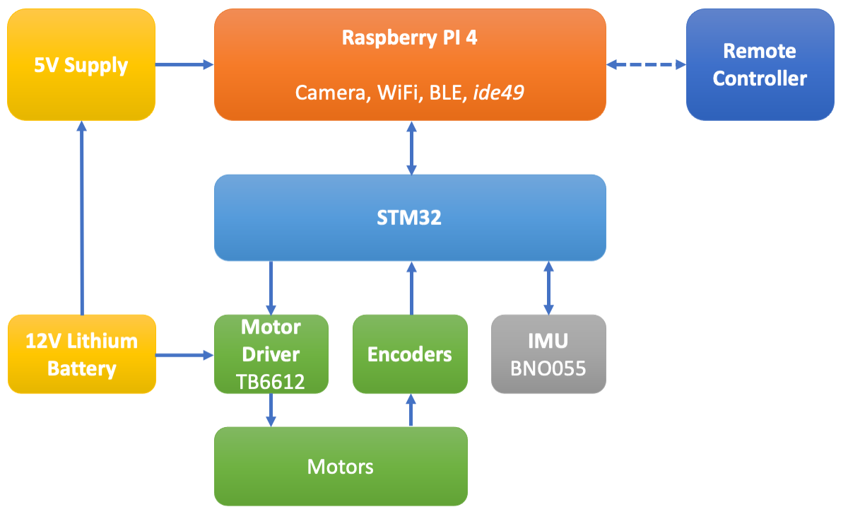
Fig. 19 Main components of the robot.#
All the “custom” electronics is combined on a small PCB in the form of a Raspberry PI “hat”. Figure 20 shows the schematic diagram.
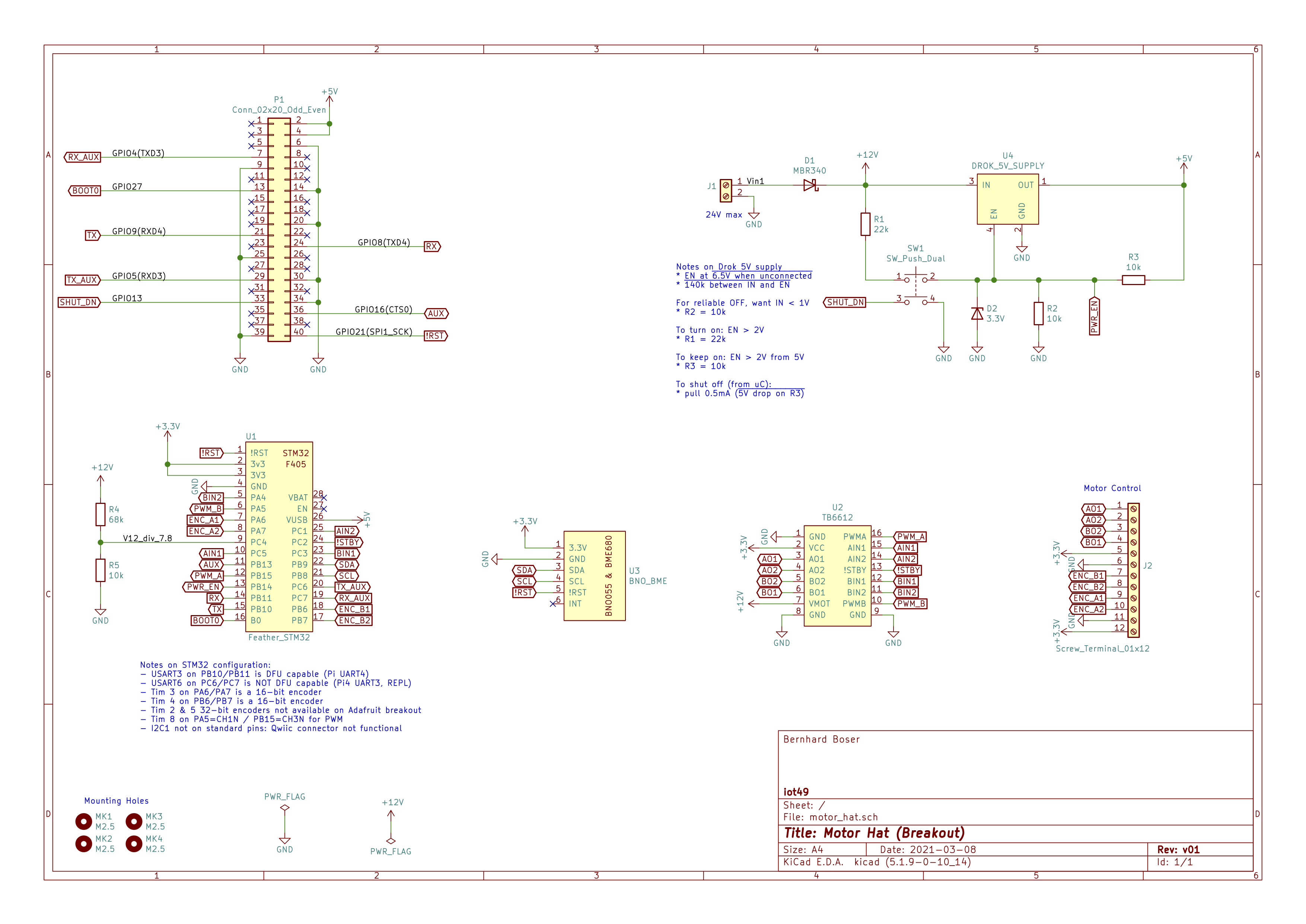
Motor & encoder connections:
Screw Terminal |
Motor |
|---|---|
AO1 drive |
black 1 |
AO2 drive |
red 1 |
BO1 drive |
black 2 |
BO2 drive |
red 2 |
3.3V |
blue 1 |
GND |
green 1 |
ENC_B1 |
white 1 |
ENC_B2 |
yellow 1 |
ENC_A1 |
white 2 |
ENC_A2 |
yellow 2 |
GND |
green 2 |
3.3V |
blue 2 |